Quantum gate simulation complexity explodes as qubit counts increase. One way to manage this complexity in simulation on classical computers is through use of decision diagrams in place of matrices. Paul Cunningham (GM, Verification at Cadence), Raúl Camposano (Silicon Catalyst, entrepreneur, former Synopsys CTO and lecturer at Stanford, EE292A) and I continue our series on research ideas. As always, feedback welcome.
The Innovation
This month’s pick is Advanced Simulation of Quantum Computations. The authors are from Johannes Kepler University in Austria. The paper was published in IEEE Transactions on Computer-Aided Design of Integrated Circuits and Systems in 2019 and has 128 citations.
The key innovation in this paper is use of decision diagrams (DDs) to significantly reduce simplify matrices and vectors which otherwise explode exponentially with increasing qubit count. This DD direction is becoming very popular in research. Further, DDs are already well known in EDA for use in formal methods and synthesis for example, making this direction appealing for our audience.
Slightly long article this time, but Paul and Raul so obviously enjoyed the topic that I felt it would be wrong to condense their input!
Paul’s view
Many years ago, while working on my PhD, I found myself reading Randy Bryant’s seminal 1986 paper on ordered binary decision diagrams (OBDDs) for the efficient representation of Boolean expressions. It was one of those “wow, so cool!” moments for me. This month’s paper applies those same ideas to quantum simulation, and it’s definitely another “wow, so cool!” moment for me.
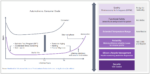
Quick recap on our first blog on Quantum simulation from December last year: an n-qubit quantum circuit operates probabilistically on all 2n possible values of those qubits. Simulating such a circuit involves forming a 2n “state vector” representing the probabilities of those qubits being in each of their 2n possible states, and then multiplying this state vector by a 2n by 2n “next state function” constructed based on the topology and connectivity of the quantum gates in the circuit. It’s conceptually very similar to how an analog circuit is simulated, just that the complexity of the problem is O(4n) vs. O(n2). The goal of a quantum algorithm is to iteratively twiddle the state vector probabilities till the right answer has close to 100% probability, and the wrong answers close to 0%.
In this month’s paper, the authors propose to construct an OBDD-like object to represent the state vector, and next state function called a quantum multi-valued decision diagram (QMDD). They observe that in practical quantum circuits, very few distinct probabilities exist in the state vector – most are zero, and the non-zero ones are often the same, or share common factors. So a BDD-like object can be constructed with very few distinct leaf nodes, especially if branches in the tree can be weighted with numerical factors. For the next state function matrix, case splitting on a qubit is done 4 ways, one for each quadrant of the matrix (think <current,next> state pair for each qubit). Again, lots of scope for compression here since matrices can be entirely composed of 1,-1,0 entries, provided some numerical factors can be applied to the 4 branches at each node of the QMDD.
Results on practical real world quantum applications are impressive. For a 30 bit quantum circuit, a classic array-based solution would need a O(1018) sized matrix. Using QMDDs on two of the most famous quantum algorithms, Grover’s algorithm for database lookup and Shor’s algorithm for integer factorization, QMDDs are only O(103) size. Simulation based on QMDDs can run these algorithms on 30 qubits in less than a minute on a 32GB desktop machine, where all other known methods have long since blown up. Nice!
Raúl’s view
As Paul explained above, quantum computer simulation on conventional computers inherently has exponential complexity. Most quantum simulation approaches prior to the paper we review this month relied on straightforward array-based representations of state vectors and matrices. For example, the paper we reviewed in December uses such an approach, simulating up to 20 qubits on a PC. Even using supercomputers with thousands of nodes and petabytes of distributed memory practical simulations historically remained limited to 50 qubits.
This month’s paper proposes a significantly improved graph-based simulation approach derived from Quantum Multiple-Valued Decision Diagrams (QMDDs), a representation inspired by BDDs (Binary Decision Diagram) and previously used successfully in logic synthesis and verification. The key insight is that many quantum state vectors and unitary matrices contain substantial internal regularity that can be captured through recursive decomposition and shared substructures. By introducing weighted edges and normalization schemes, the decision diagram compactly encodes sub-vectors and sub-matrices, yielding much smaller data structures for many practically relevant quantum computations.
The paper further describes efficient algorithms for the key operations required in quantum simulation, including Kronecker products, matrix-vector multiplication, and quantum measurement (which collapses superposition). Because the decomposition closely matches the recursive structure of quantum operators, many operations reduce to localized manipulations of the decision diagram rather than traversal of exponentially large arrays.
As with conventional decision diagrams, the worst-case complexity remains exponential: in the absence of exploitable redundancy, the representation degenerates into a full binary tree with 2n nodes. However, for highly structured quantum circuits, the representation often grows only linearly with the number of qubits, allowing simulations far beyond the reach of array-based techniques.
Researchers had explored graph-based representations based on BDDs before, e.g. Quantum Information Decision Diagrams (QuIDDs), but Advanced Simulation of Quantum Computations is cited as foundational and reported greatly improved results. The simulator achieved Grover algorithm simulations with 40 qubits using only approximately 52 MB of memory, and Shor algorithm simulations with 37 qubits using about 260 MB, all on a small four-core desktop machine. Quantum Fourier Transform (QFT) circuits showed especially favorable scaling, with successful simulations up to 64 qubits.
To put this in context, Intel’s qHiPSTER simulator projected in 2016 that simulating 48–49 qubits would require between 4 and 10 petabytes of distributed memory. More recently, the Jülich Research Center reported a full simulation of a 50-qubit universal quantum computer in 2025 using approximately 2 petabytes of memory.
Subsequent research exploiting structural regularities in quantum circuits through these techniques has demonstrated near-linear scaling behavior for structured implementations of Shor’s and Grover’s algorithms, enabling simulations exceeding 100 qubits. More recently, researchers reported the factorization of the number 1011 using a 42-qubit simulation of Shor’s algorithm running for approximately five hours on a Windows laptop.
In the end, however, you can’t escape the fundamental exponential complexity of quantum computation relative to classical von Neumann machines. Advanced simulation techniques can significantly extend the practical limits of quantum simulation, making it a useful tool for the design, development, debugging, and verification of quantum algorithms and architectures — but not a replacement for the real thing. This is similar to simulation in EDA: indispensable for building complex systems, much slower than the hardware being modeled.
Also Read:
Quantum Gathering Momentum Amid Concerns for the Grid
PQShield unveils ultra-small PQC embedded security breakthroughs at Embedded World 2026