By Zameer Mohammed
Once a chip is taped out, changes in design are not possible – Silicon is unforgiving, does not allow postproduction modifications. In contrast, software can be updated after release, but chips remain fixed. Static Timing Analysis (STA) signoff serves as a crucial safeguard against silicon failures.
In modern VLSI design, errors are extremely costly, impacting finances, time-to-market, product credibility, and safety for critical applications. Missing just one STA check can result in multimillion-dollar losses and significant project delays.
“Only Paranoids Survive – a cautious and thorough approach is essential for STA signoff”
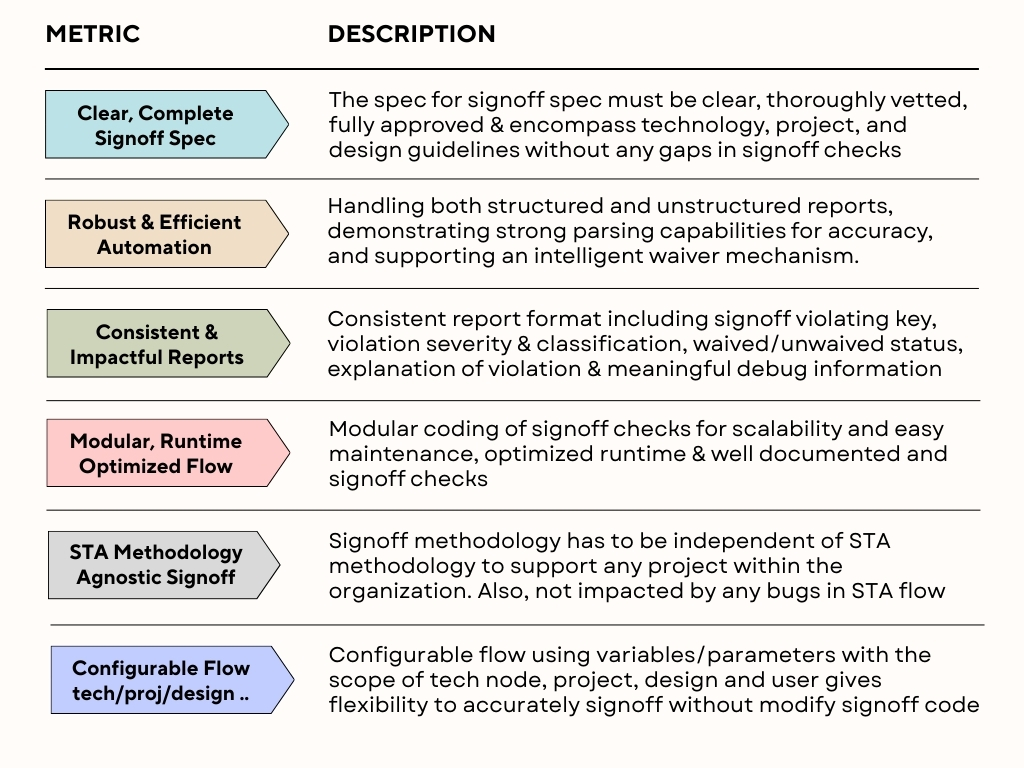
Objectives of a good STA Signoff Methodology
- Comprehensive set of signoff checks – every detail examined
STA signoff checks are required to meet the specifications established by technology, design, project, and blocks. These signoff checks must identify structural issues, verity correct STA execution, perform all mandated timing analyses, and incorporate any custom checks relevant to the specific node or design.
- Ensure flawless signoff without errors or omissions
Conducting a comprehensive review of signoff specifications and code implementations, coupled with the integration of automated processes and log parsing for all signoff output logs and reports, alongside the proper application of waivers and effective communication regarding un-waived signoff violations, is critical for ensuring robust STA Signoff quality.
- Find pessimism in signoff specifications and extreme constraints
The STA signoff process should efficiently identify unrealistic constraints and provide robust debugging reports. Structuring reports by violation type, severity, design, and operating mode – supported by clear charts and statistical summaries such as frequency histograms – significantly improve clarity. Additionally, early identification of inflated requirements is essential to ensure effective STA signoff.
- Early timing closure feedback to resolve issues proactively
Prioritizing essential signoff checks that could lead to future bottlenecks, along with providing clear feedback, debug data, and proposed solutions, help achieve a faster Timing Closure cycle.
Key Attributes of STA Signoff Methodology

While it’s beyond the scope of this article to go over detailed algorithm of each of the STA signoff checks, a single signoff check is presented here with details.
Crosstalk on Nets – Custom STA Signoff Check Crosstalk
Crosstalk complicates timing closure by causing pattern-dependent and corner-sensitive delay variation that can break both setup and hold times. It introduces noise that may lead to the glitches, false captures, and increased jitter, reducing overall design margins. Crosstalk also negates CPPR credit and negatively affects both capture and launch for the same timing path due to worst case analysis. Block to top miscorrelation is also attributed to crosstalk on boundary nets. This could force costly ECOs involving re-routing, shielding with potential ripple effects on power, DRC and EMI closure.
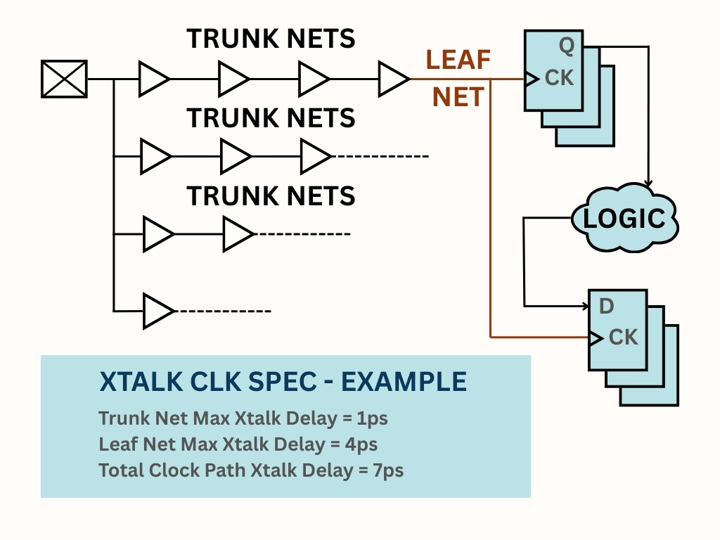
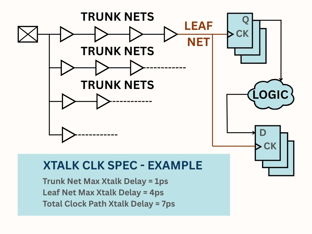
It is important to set crosstalk limits for datapath, clock trunk and clock leaf nets, and to verify each net in design. An example is presented below with details.

Trunk Nets are generally targeted to have zero crosstalk delay component, as excessive crosstalk can complicate timing closure. Common methods of crosstalk mitigation include double spacing and shielding. On critical routes, differential clock routing maybe employed. In practice, some nets may not meet this target, so establishing a conservative and reasonable crosstalk limit is recommended. The goal is to maintain a crosstalk clean clock trunk network. Because each path can involve large number of nets, it’s vital to keep the clock trunk network free of crosstalk, as it accumulates along the path.
Leaf Nets cannot be shielded or isolated since they represent the final stage of clock network and are connected to an equal number of sequential devices making shielding and isolation (by double or triple spacing) resource intensive. Consequently, it is generally acceptable to allow 4-5 ps of crosstalk on each leaf net. To manage potential issues, a cumulative limit can be established for total crosstalk along the nets in clock path, enabling oversight of both excessive crosstalk on individual leaf nets and combined effect from the trunk and leaf net crosstalk.
A structured approach involves analyzing 1000 paths per clock domain for example, collecting all nets pertaining to the capture clock path, and extracting delays associated with cross coupling effects. Constructing a frequency distribution table with crosstalk delay intervals ranging from 1ps to 10 ps facilitates assessment of the clock network’s performance in relation to cross coupling. Additionally, performing this signoff verification and comparing results consistently provides an early indication of any clock network degradation. Prompt identification of issues as they arise is essential for effective Timing Closure.
Categorized “STA Signoff” checks & description
The list of STA signoff checks is very comprehensive, with at least 50 signoff checks; here are the key ones with brief description. Detailed coverage of all checks is outside the scope of this article.
- STA Signoff Spec Implementation Check – First Signoff Step
STA Margins – Verify margins and guard bands applied for each relevant check, whether tool-generated or user-defined.
Timing Derates – Check Process, Voltage, Temperature, Aging, Radiation, MixVT and distance based derates for design /cell /net / constraints / checkTypes.
Clock Uncertainties – Check clock uncertainty specification based on clock period percentages or a flat number for each clock or design.
Full Cycle Jitter – Measure Jitter, modeled as additional clock uncertainty and usually specified as compounded root mean square sum of PLL jitter and CTS network jitter.
Half Cycle Jitter – Similar to full cycle jitter, measure jitter applied to half cycle paths and min pulse width checks.
Input Drive – Check for presence of driving cell and confirm either the default or custom driver for each port based on PVT conditions during timing analysis.
Output Load – Verify the default minimum load, and custom loads based on presence of I/O pads or special external specifications for output drivers.
STA Flow Variables – Hundreds of variables steer accurate signoff STA, requirements dictated by tool version, technology node or foundry specification, project intent, STA methodology and signoff specification.
STA Command Options – Same details as STA Flow Variables applies to options used in Commands to execute STA steps.
STA Corners – Check to ensure signoff spec matches the STA corners for which analyses is performed. (PVTRC x Functional/Scan/JTAG/CDC …)
Max Transition Limits – Verify that max transition reports reflect minimum library constraints and any over constraint on clock domains or designs set by project/design to achieve superior timing performance.
Max Cap Limits – Same details as Max Transition Limits apply to Max Capacitance checks. Usually, library defaults used for internal nodes.
Asynchronous Clock Groups – Collect timing paths with finite slack from all clock group combinations, and trace master and generated clocks to determine clock crossings from reported paths that are not part of same family.
- Input Acceptance Criteria – Preventing Junk In Junk Out scenario Netlist Quality – Confirm accurate read design process and check for any netlist structure or hierarchy binding errors or warnings.
Timing Constraints Quality – Ensure accurate reading of constraints files, free from unwaivable errors and warnings, confirm the correctness of master and generated clock definitions, and verify the proper implementation of timing exceptions.
Annotation Parasitics Quality – Check correct read of parasitic annotation files, audit extraction logs for signoff (layers, flow variables, log parse of extraction files, correct tech file usage, inclusion of metal fill, location information in parasitics if applicable).
Design Library Usage Correctness – Verify correct library usage for standard cells, io pads, memories, custom IPs from various choices within released library database.
Tool Versions Correctness – Correct tool versions for timing, extraction, constraint generation, IP model generation & Unix usage (csh, python, lsf/bsub…)
File Versions – Check correct versions of files for Variation (POCV/SOCV), Power Configuration (UPF), Netlists (.vg, .libs), Parasitics (SPEF), STA Flow Versions.
- Structural Checks – Significant flaws in design construction, backup STA checks Don’t Use Cells – Clock & Data don’t use cells as per foundry, project and block spec based on cell type, cell strength and placement in timing path.
Must Use Cells – Clock & Data cell types (flop types, clock buffers, i/o drivers …)
Synchronizer Cell Types – Check specific allowable pattern for stage1 and stage2 synchronizers (library cell, strength, vt type)
Synchronizer Cell Proximity – Check to ensure 2 stages of synchronizers abut with each other or placed right next to each other for optimal metastability failure times.
Synchronizer Cells Structure – Check to ensure only net and no cell exists in between 2 stages of synchronizers.
Delay Cells & Structure – Check to ensure right delay cell type and strength, and maximum number of allowable contiguous delay cells in a timing path, to ensure no optimism in delay cell variation modeling.
Lockup Latch Structure Correctness – Half cycle path lockup latch capture polarity correctness (can’t rely on external tools), lockup latch cell type and placement of lockup latch close to launch clock (destination can absorb clock skew not source)
Sparecell Density – Check sparecell density spec per block.
Port Fanout – Ensure single fanout of all critical data or clock ports to avoid overload in upper-level instantiations, and to ensure block/top correlation related to spatial derates bounding box.
Input Port Net Length – Ensure optimal net load when modules are multiply instantiated at higher levels.
Timing Path Depth – Every clock domain examined for critical path depth, a finite limit must be ensured for low risk down the timing closure phases, also an early indicator of timing convergence risks if done pre-layout STA.
Power Management Cell Structure – Cell type and correct instantiation of isolators, level shifters, enable level shifters, voltage interface cells, retention flops, retention memories, power switches, reset isolation cells, always on buffers, clamp cells & bus hold cells.
VT Type Usage – Percentage usage of various VT flavors as per spec for each block and chip overall usage.
MixVT Usage – VT spec is based on single VT usage for clock or datapath. If MixVT is used, additional VT penalty must be applied. Check is necessary to detect MixVT and fix structure of design, or apply additional margins/derates.
- STA Run Correctness Checks – Signoff Process Validity
Design Linking – Check to see if all designs linked, any port mismatches, empty modules, black boxes etc. Crucial to make sure every design element is timed, and every single timing arc is covered without going into analysis coverage debug.
Parasitic Annotation Coverage – Ensure all nets annotated with Resistance, Ground Capacitance and Coupling Capacitance, also checked for floating/dangling nets.
Correct Spef Transformation – When multiple SPEFs stitched at higher levels, correct orientation and block size must be read in via PDEF or custom commands, for correct distance calculations used in distance based derates. Also, can’t trust any tool with correct calculation even though tools handle design origin and orientation automatically. This check is very crucial to also cover issues like not reading such location details from SPEF files etc.
Constraints Analysis Coverage & Quality – Unclocked sequential cells and untimed timing endpoints in the context of STA analysis mode are two most critical coverage items for every STA check. Additionally conflicts in case analysis, ignored exceptions, master clock non propagation to generated clocks, any constraints non propagation.
Derates & Margins Coverage – Check derates application for cell, net, constraints (setup, hold, min pulse width) related to Process, Voltage, Temperature, Aging, Radiation, mix VT usage. Also check guard bands or margins for pre-layout, block specific or additional signoff pessimism.
Log Parsing -Most important signoff step, every error or warning must be flagged, reviewed, waivers validated and closed before a thumbs up for tapeout or STA signoff. This must be run with every block, every regression of STA in automated mechanism. No Excuses.
PBA/GBA Convergence – Most PD tools and STA under the hood run GBA and then perform PBA analysis with GBA baseline. 100% coverage for PBA is achieved by various custom algorithms. When tools can’t converge, they fall back to GBA timing on those specific paths and issue messages about non convergence. Checks must be done to ensure 100% PBA GBA convergence to remove pessimism is timing (which is not harmful, but not accurate and time consuming to close on GBA timing)
STA Units Correctness – SDC time units, Capacitance units, Resistance units – SDC unit are specified in sdc, decoded from library read or set in STA flow. Each tool has difference precedence rules to interpret units. And correct usage is essential to interpret SDC. Reporting units are different from library units. Library units handled by tool whereas reporting units help STA users interpret reports with consistency and known formats.
STA View Completeness – Check to make sure all functional and scan modes, and all PVTRC analysis corners have been analyzed based on project specification.
STA Run Completeness – Based on all STA views executed, make sure each run ended correctly, all phases of STA executed, and job status from Unix/LSF/BSUB had no unexpected termination, any issues in STA due to disk failures, TMP space, additional license availability etc.
- STA Metrics Checks – The real STA checks for signoff Standard Timing Path Checks – Setup, Hold, Recovery, Removal, Clock Gating, Data to Data Checks.
Design Rule Checks – Max Transition(slew), Max Capacitance, Max Fanout
Special Checks – Min Period/Clock Period, Min Pulse Width, Noise, Double Clocking.
- STA Custom Checks – Additional robustness check for high quality STA signoff
Max Clock Skew – Skew is never a criterion to signoff as its impact is already absorbed in various timing violations, but excessive skew can expose variation modeling flaws and can cause silicon failures, it’s a good practice to have reasonable limit on skew in any path.
Excessive Xtalk – Crucial component of timing closures, hurts both setup/hold simultaneously, lethal for checks like Min Pulse Width. Exacerbates block to top correlation, impacts Common Path Pessimism Removal (CPPR) credit and impacts cell/net delays in any path. Proper limits must be set in terms of coupling cap or delays or transition times for coupled nets for datapath and clocks.
Dynamic Jitter Validation – For each clock domain, calculate dynamic jitter by compounding source PLL jitter with CTS network jitter (root mean square of each stage element CTS network jitter) and validate against per clock domain jitter spec. Used only in high performance designs where we its very conservative to apply flat jitter number to all clocks or groups of clocks.
Half Cycle Paths – Custom timing reports to analyze half cycle paths as they have half cycle jitter and custom uncertainties and margins, IP interfaces, scan paths etc.
And the list is endless – Based on technology node, company STA philosophy, signoff owner paranoia, sky is the limit to custom STA checks.
Failure to implement the STA signoff methodology outlined above will lead to frequent bugs, negatively affect Time to Market, incur expensive design fix cycles, and diminish the credibility of the signoff process, which is the most critical factor.
Zameer Mohammed
Zameer Mohammed is a timing closure and signoff expert with over 25 years of experience, having held key technical lead roles at Cadence Design Systems, Apple Inc., Marvell Semiconductor, Intel, and Level One Communications. He specializes in STA signoff for complex ASICs, with deep expertise in constraints development and validation, synthesis, clock planning, and clock tree analysis. Zameer holds an M.S. in Electrical Engineering (VLSI Design) from Arizona State University and is a co-inventor on U.S. Patent No. 9,488,692 for his work at Apple.
Also Read:
Orchestrating IC verification: Harmonize complexity for faster time-to-market
Perforce and Siemens at #62DAC
Synopsys Enables AI Advances with UALink
Share this post via:


TSMC vs Intel Foundry vs Samsung Foundry 2026