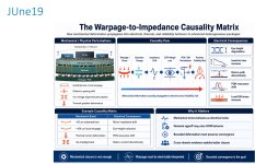
The Warpage-to-Impedance Causality Matrix
In advanced packaging, warpage is often treated as a mechanical or assembly problem.
But in large AI packages, chiplets, HBM, glass substrates, bridges, interposers, and high-speed package-to-board transitions, warpage is no longer only mechanical.
It becomes electrical.
A substrate that bows by 50–100 µm may still look like a geometry problem.
But that deformation can change:
dielectric spacing
via alignment
return-current continuity
local impedance
insertion loss
PDN resonance
thermal-current interaction
EM stress
SI/PI margin
This means mechanical stress can behave like electrical noise.
That is the blind spot.
Traditional flows often separate mechanical closure from electrical closure. The mechanical team evaluates warpage. The SI/PI team validates margin. The package team checks assembly limits. The board team checks routing and return paths.
But the system does not fail by organization chart.
It fails through physical causality.
A local substrate bow may shift impedance.
An impedance shift may reduce eye height.
Reduced eye margin may trigger link instability.
Link instability may increase retraining.
Retraining and compensation may change power behavior.
Power behavior may reshape thermal gradients.
Thermal gradients may increase long-term reliability risk.
That is why warpage should not be treated only as a pass/fail mechanical threshold.
It should be treated as a bounded electrical perturbation.
The goal is not perfect geometry.
The goal is bounded convergence.
A Warpage-to-Impedance Causality Matrix asks:
How much deformation occurred?
Where did it occur?
What electrical path did it perturb?
How did impedance change?
What happened to SI/PI margin?
Did PDN behavior shift?
Did EM or thermal-current risk increase?
Is compensation possible?
Is the system still inside a trusted operating boundary?
This is especially important as packaging moves toward larger substrates, glass cores, CoWoS, CoPoS, chiplets, HBM, optical I/O, and 2.5D/3D integration.
In that world, mechanical closure is not enough.
Electrical closure is not enough.
Thermal closure is not enough.
The real challenge is preserving causality across domains.
Warpage must be mechanically measured, electrically interpreted, thermally contextualized, and reliability-qualified.
The package is no longer a static structure.
It is a coupled physical system.
And in advanced heterogeneous systems, the future of signoff may depend less on isolated domain closure and more on whether physical variability can be traced, bounded, and governed across the full system corridor.
Mechanical stress is not just stress.
Sometimes it is the first signal of future impedance failure.