Array
(
    [content] => 
    [params] => Array
        (
            [0] => /forum/threads/electro-optical-realization-corridor.25327/
        )

    [addOns] => Array
        (
            [DL6/MLTP] => 13
            [Hampel/TimeZoneDebug] => 1000070
            [SV/ChangePostDate] => 2010200
            [SemiWiki/EmailDomainReplace] => 1000010
            [SemiWiki/Newsletter] => 1000010
            [SemiWiki/WPMenu] => 1000010
            [SemiWiki/XPressExtend] => 1000010
            [ThemeHouse/XLink] => 1000970
            [ThemeHouse/XPress] => 1010570
            [XF] => 2031070
            [XFI] => 1060170
        )

    [wordpress] => /var/www/html
)

Electro-Optical Realization Corridor

moh.kolb

New member
CPO and optical I/O are often described as “light replacing copper.”

I think that framing is incomplete.

Before data becomes optical, the electrical launch still has to close. After conversion, the optical path still has to be attached, powered, aligned, cooled, coupled to fiber, tested, and qualified.

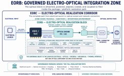
That is why I frame this as an Electro-Optical Realization Block, or EORB, inside a broader Electro-Optical Realization Corridor.

The modulator or optical engine may be the device breakthrough. But the product is the full realization path:

electrical launch
optical conversion
driver integration
package/substrate interface
alignment stability
thermal drift control
fiber attach
SI/PI behavior
test coverage
yield learning
lifecycle reliability

This is especially important for CPO, silicon photonics, and future AI/HPC optical interconnects.

The winning architecture will not be the one with the best optical device alone. It will be the one that proves the full electro-optical corridor can be manufactured, tested, cooled, aligned, and trusted at scale.

Light may solve distance.

Governed electro-optical realization determines whether it scales.
 

Attachments

  • Picture1_EORB_SEMI_JUNE17.jpg
    Picture1_EORB_SEMI_JUNE17.jpg
    235.9 KB · Views: 137
One additional point:

The optical path is not only attached, powered, aligned, cooled, and coupled to function inside the package.

It is attached, powered, aligned, cooled, coupled, tested, yielded, and governed to become part of a trusted realization path.

Light may solve distance.

Governed electro-optical realization determines whether it scales.
 
Additional points:

Replacing long copper electrical paths with optical links can reduce reach-related loss, improve bandwidth density, lower some power burden from high-speed electrical signaling, and reduce signal-degradation issues over distance.

But I think the key point is that optics does not remove the full power and thermal problem — it relocates and changes it.

The optical engine still needs drivers, TIAs, lasers, coupling, thermal control, alignment, test, yield, and serviceability. So CPO helps solve the copper reach and bandwidth wall, but it also creates a new electro-optical realization challenge inside the package and system.

That is why I see CPO not only as “replacing copper,” but as building a manufacturable optical connectivity path that can scale reliably in AI infrastructure.
 
This is a great point about moving from just a working lab prototype to a trusted, real-world product. Even if a microscopic optical laser aligns perfectly on day one inside a cleanroom, running intense AI workloads makes these chips incredibly hot, which can physically warp the packaging materials over time.
How are companies planning to govern and monitor these chips over their lifespan? Are they building tiny sensors directly inside the chip architecture to actively adjust the lasers as the hardware ages?
 
Great question.

Day-one optical alignment is not enough for CPO.

In real AI systems, thermal gradients, workload cycling, material expansion, laser drift, coupling variation, aging, and package stress can all shift the electro-optical path over time.

So yes, companies will need embedded sensing and feedback: temperature sensors, monitor photodiodes, laser power tracking, wavelength and bias control, link-margin telemetry, firmware calibration, and package reliability models.

But the key is not just adding sensors.

The system must turn those signals into causal, trusted, decision-ready evidence.

Optical power drift is only a symptom. The cause could be laser aging, thermal shift, coupling loss, package deformation, driver behavior, or workload-induced heating.

That is why CPO is not only an optical-engine problem.

It is a lifecycle-governed electro-optical realization problem.
 
Back
Top